Non-photorealistic Volume Rendering with Stipplinge-mail Raymond Li (presentation)
IntroductionThe authors of [1] simulate hand-drawn techniques for rendering volumes. They specifically target stippling in their paper. Stippling uses dots to give the impression of shading, light, silhouettes, boundaries, and structure. A region with more stipples usually means a higher density or a boundary. Biological and medical illustration frequently utilize stippling to artistically enhance regions of interest. [2] My objective is to implement the stipple rendering engine so that volume data sets could be rendered with stipples. The original goal was to get the basic stippling engine functioning and then add the various feature enhancements. As it turns out, the silhouette curves is more interesting and adds a lot of detail to the rendered image. My implementation includes two feature enhancements: boundary enhancement and silhouette enhancement. In addition, silhouette curves is implemented. EquipmentThe project is done on a Dell Inspiron 5100 laptop with an ATI Radeon Mobility 7500 video card. The Windows XP operating system is installed on the laptop. The implementation is done in the C++ programming language using FLTK for the graphical user interface. Stippling Theory and ImplementationThe set-up for stippling puts the volume of interest centered at the origin. This avoids having to do translations for volume rotation. The volume is viewed down the z-axis and volume data points are first rotated and then point rendered to the image plane. Point rendering is an object order viewing method and orthogonal projection is used in this implementation. The implementation in the paper uses a cube with a width of at least 5 pixels to represent each voxel. The idea is to represent voxel attributes like intensity, boundary, silhouettes, and lighting with stipples in a cube. The number of stipples in the cube is directly related to these attributes. This "mapping" from voxel attributes to stipples in a cube is the underlying reason a larger volume is needed to represent the voxel. The maximum number of stipples (Nmax) permitted in the cube must be less than volume of the cube. Otherwise, the rendered image is too dark. The paper uses a heuristic formula to adjust the maximum number of stipples in a cube. The authors use a Poisson disc distribution to position the stipples. This has the effect of creating a uniformly random distribution of stipples in the cube. My implementation represents each voxel with a square as opposed to a cube. This most likely has the effect of producing a rendered image that is not quite as sharp as the cube representation. However, the results are acceptable. My implementation makes the maximum number of stipples (Nmax) in the square a user-adjustable percentage of the area of the square. Also, instead of the Poisson disc distribution, a simple random distribution is used since the area of the square is already so limited that the Poisson disc has little effect. Feature EnhancementsThe formula for stipple count in the cube (or square) is: Ni = Nmax * T T represents the feature enhancements: T = Tb * Ts Tb and Ts are the boundary and silhouette feature enhancements, respectively. Both are normalized in the range of zero to one. Boundary Enhancement. Stipple drawings normally have increased concentrations of stipples near boundary regions. This is the formula used for boundary enhancement: Tb = vi * (kgc + kgs * (gradient_magnitude ^ kge)) vi is the voxel intensity. kgc, kgs, and kge are user-adjustable constants. Silhouette Enhancement. In stipple drawings, silhouettes are found where the gradient vector is orthogonal to the eye vector. This is the formula that enhances the silhouette: Ts = vi * (ksc + kss * (1 - (abs(gradient_vector . eye_vector))^kse) Again, vi is the voxel intensity. ksc, kss, and kse are user-adjustable constants. Silhouette CurvesThe authors claim stipple drawings often outline the volume and important interior features. The stipples provide density, structural, and lighting cues. The paper finds these outlines through edge-enhancement, specifically the Laplacian of Gaussian (LoG). My implementation uses an 11x11x11 LoG kernel with sigma=1.4. The 3D convolution is performed before any rendering occurs, specifically when the volume is read for the first time. The result is an edge-enhanced volume that is used as one criteria in determining whether to draw a silhouette curve. The three criteria are as follows:
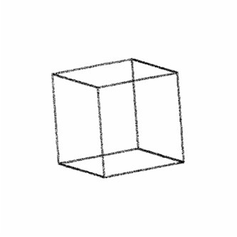
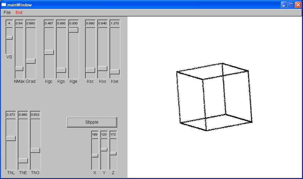
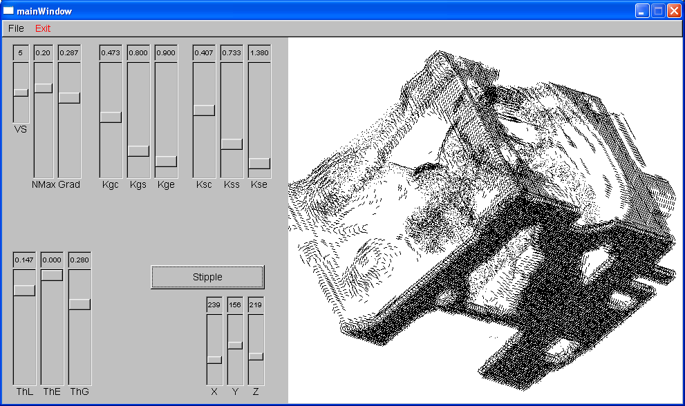
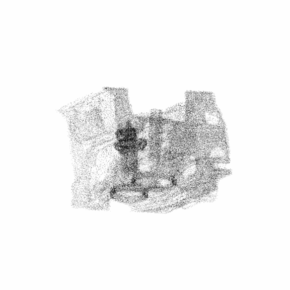
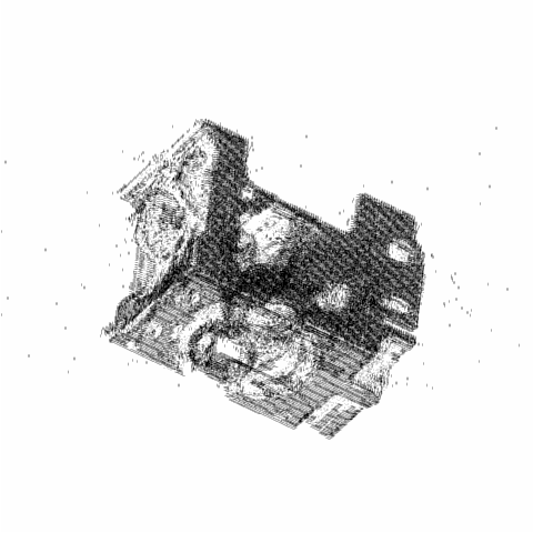
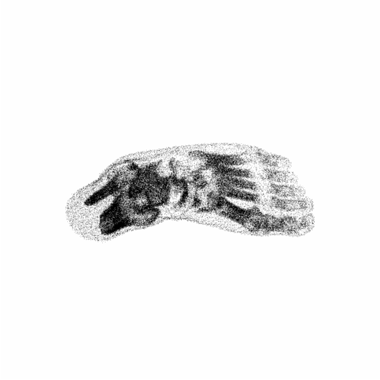
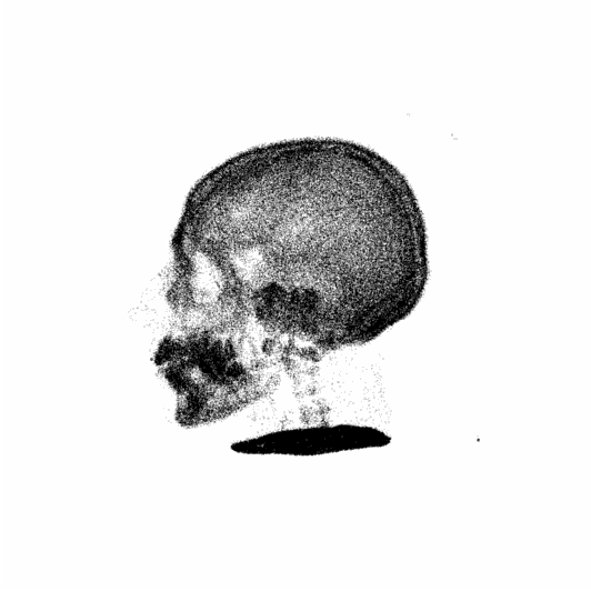
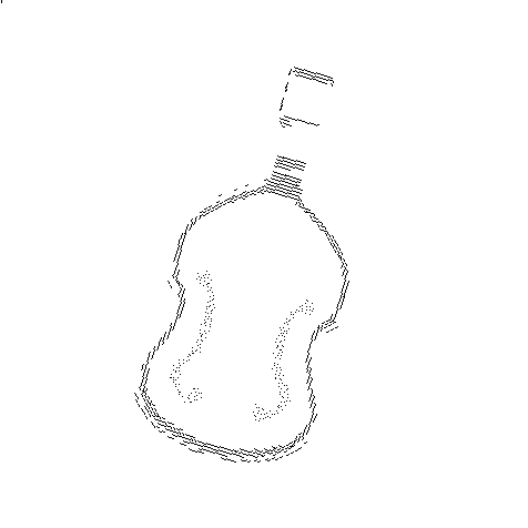
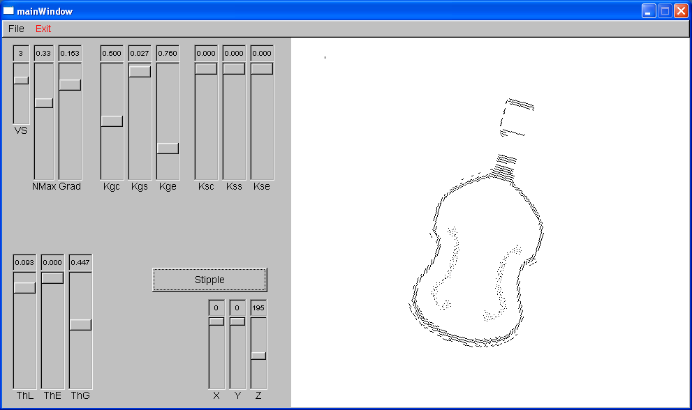
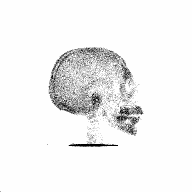
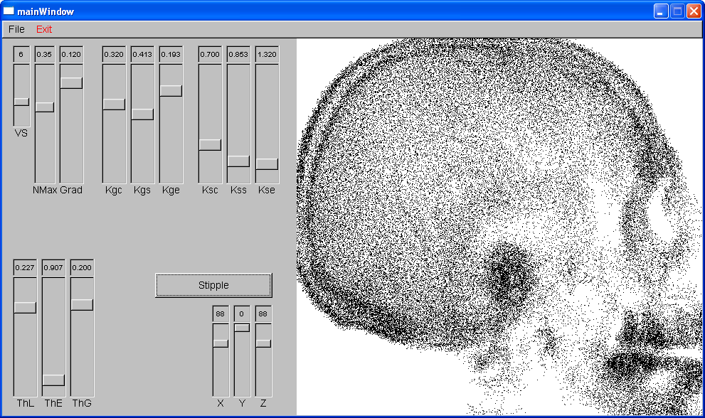
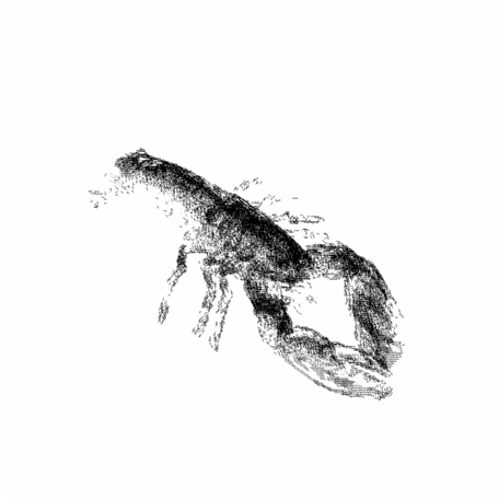
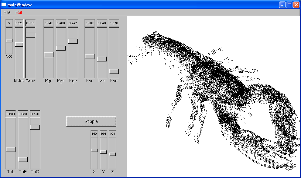
If all criteria are satisfied, a line is draw through the center of the cube (or square) in the direction of (gradient_vector x eye_vector). ResultsA stipple volume rendering engine is successfully implemented with boundary and silhouette enhancements. In addition, silhouette curves are also implemented. The rendering engine is very fast even without hardward acceleration. After the volume dataset is read (and the convolution is finished), each rendering of the sample volume datasets took no longer than about 10 seconds. Please view the example images below: References
|